[Special and huge thanks to Scott Lowe for answering an endless amount of questions I had while writing this post and testing with NSX/OVS over the last few days. Thanks to Deepesh as well who I bounced OVS questions off of when I needed to give Scott a break. ]
In Open vSwitch 101, I described the three main components that make up Open vSwitch (OVS) from an architectural standpoint, namely ovs-vswitchd, ovsdb-server, and the fast path kernel module. If you start to work with OVS, the first thing you realize is that it takes quite a bit more knowledge to really understand it. This post will focus on some design principles and options when running OVS on a hypervisor like KVM in conjunction with a network virtualization solution.
In Open vSwitch 101, I described the three main components that make up Open vSwitch (OVS) from an architectural standpoint, namely ovs-vswitchd, ovsdb-server, and the fast path kernel module. If you start to work with OVS, the first thing you realize is that it takes quite a bit more knowledge to really understand it. This post will focus on some design principles and options when running OVS on a hypervisor like KVM in conjunction with a network virtualization solution.
To make this a little more practical, we will use a scenario which consists of a KVM host with 3 physical NICs – 1 x 1G and 2 x 10G. The 1G interface will be used for management and the 2 x 10G interfaces will be used for actual transport of VM traffic.
This example will also assume the use of an overlay network virtualization solution to be used for all VM-data traffic leaving the host that leverages OpenFlow/OVSDB to communicate between the controller and OVS.
If we take this scenario, we know we will need to connect multiple virtual machines and three physical interfaces to OVS, which logically looks like the following diagram.
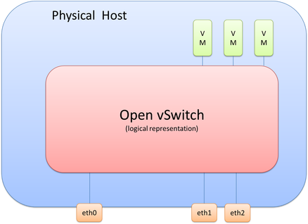
It’s important to realize that picture is only a logical representation of OVS. The details of this have a few moving parts that I’ll break down throughout this post.
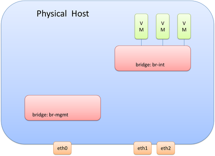
In deployments that leverage OVS in conjunction with OpenFlow/OVSDB network virtualization solutions like NSX or even with OpenDaylight+OVS, it is good practice to separate the bridge that the VMs connect to vs. the bridge(s) for everything else. One reason for this is that the SDN or Network Virtualization controller will be making changes to the bridge and it is good practice to isolate these changes to a single bridge that only the VMs connect to. The bridge that the VMs connect to is called the integration bridge and is often identified as ‘br-int’ when on the Linux command line.
From a management interface perspective, we’ll also look at using OVS, although using the traditional configuration of assigning the interface the management IP Address directly is also a valid design/configuration. Since we won’t be connecting the management interface to br-int, we will need another OVS bridge to connect the mgmt. interface to. Let’s call this bridge ‘br-mgmt.’ This would look like the following diagram. Remember, we still haven’t covered eht1 and eth2, but that is coming.
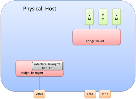
At this point, there are two bridges within OVS created. Each bridge is a layer 2 construct. As stated previously, one option for the management interface is to assign the mgmt. IP directly to the interface, but we aren’t going to be doing that here. While each bridge is a layer 2 construct at this point, it is in fact possible to assign a layer 3 address (equivalent to an SVI) to this bridge. When each bridge is created, there is an internal port created that has the same name of the bridge itself. It is on this internal port where an IP address is assigned. Thus, it is the internal port called br-mgmt on the bridge called br-mgmt that will be assigned the management IP Address. Adding the IP address for the management network would look like this:

In order to complete the connectivity for the management interface (eth0), we will need to connect eth0 to the br-mgmt bridge. This means br-mgmt will essentially have two interfaces – one that connects to eth0 and one that connects to the internal port br-mgmt that has the Layer 3 interface assigned to it. This can be seen here:
Note: it may be advantageous to assign the IP address required for management directly to the interface and not use OVS. This may make it easier and less error prone during OVS upgrades.
Remember, the last thing we just did for br-mgmt was connect eth0 to br-mgmt.
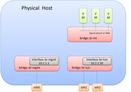
Now we need to actually do something similar with the physical interfaces that will be used for data (overlay transport), i.e. eth1 and eth2. As stated previously, it is generally good practice not to have any physical interfaces connected to br-int. This means we will need a separate bridge for eth1 and eth2. A bridge, often called br-tun in overlay solutions, can be created and eth1 and eth2 can be connected to this newly created bridge. This looks like so:
Remember, the last thing we just did for br-mgmt was connect eth0 to br-mgmt.
Now we need to actually do something similar with the physical interfaces that will be used for data (overlay transport), i.e. eth1 and eth2. As stated previously, it is generally good practice not to have any physical interfaces connected to br-int. This means we will need a separate bridge for eth1 and eth2. A bridge, often called br-tun in overlay solutions, can be created and eth1 and eth2 can be connected to this newly created bridge. This looks like so:
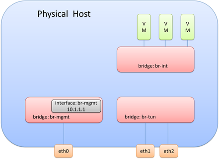
Since this design is used for overlay traffic, it needs to act as a tunnel endpoint (TEP) device (basically it needs an IP Address to source and terminate tunnels). This IP Address will be created the same way the management IP Address was created. It will use an internal port called br-tun on the bridge called br-tun.
At this point, the OVS diagram would look like this following picture.
At this point, the OVS diagram would look like this following picture.
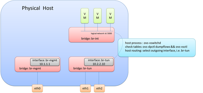
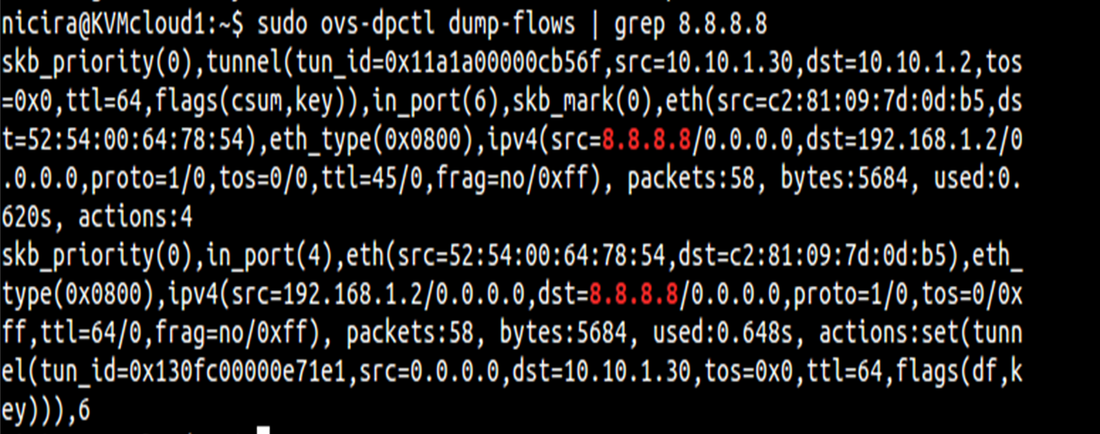
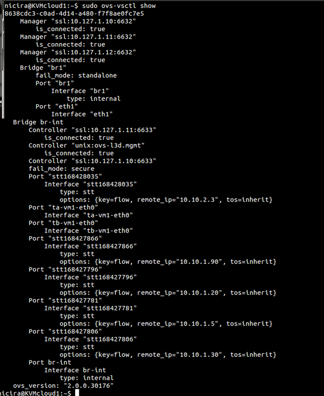
What you may notice is that br-tun does not actually connect to br-int. Is a connection required here? While you may want to say yes, the answer is actually, no. This may seem confusing at first, but what happens is as traffic is received from interfaces on br-int, it will examine the flow table and cross check the known overlay interfaces on ‘br-int’ to figure out which host (hypervisor) the destination VM resides on. To view this data yourself, you can use ‘ovs-vsctl show’ and ‘ovs-dpctl dump-flows’. By examining these outputs, you will be able to see which logical interface on br-int should be used for egress tunnel traffic and what the remote TEP address is.
Note: This logical tunnel interface was programmatically provisioned by the NSX controller via OVSDB and could be of type STT, VXLAN, or GRE. In this case, it was actually STT (as you’ll see in the pictures below). This isn’t something you would do manually, unless of course, you aren’t using a central controller.
Okay, we now know the destination TEP and the logical interface to forward it out of, but what now? The interesting and very important piece of information to note is that the packets being forwarded now become a function of the host (hypervisor) itself. To be more specific, it will use the host process within OVS, ovs-vswitchd, to forward the traffic. And what this really means is that it will use the host routing table. If the destination/remote IP on the tunnel interface is X, the routing table will check how to get to X. Based on route recursion it will recurse to a directly connected interface, and this traffic will be egressing using the source IP address configured on the internal port previously configured on ‘br-tun’, i.e. the directly connected interface.
To bring this all together, the original frame and packet is encapsulated and as it egresses from br-tun, the source MAC/IP will be from the internal port on br-tun, the destination MAC will be the default gateway/router MAC on the segment (unless the remote IP is on the same segment), and the remote IP is the IP address of the tunnel endpoint (TEP) of the remote hypervisor.
Note: an OVS port can have multiple interfaces in order to perform bonding. This is implied here and the step to create a bond wasn’t covered here.
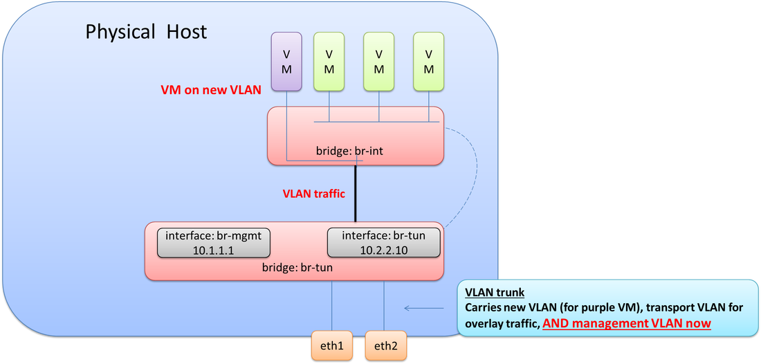
This design would be a working design for 100% overlay traffic, but what if you needed VMs to be on a VLAN on the same physical host that the overlay traffic is on.
Thinking this through, you may realize, an 802.1Q trunk would be required between eth1 & eth2 and the physical network, e.g. between br-tun and the physical network. This means at least two VLANs would need to be configured on br-tun. One VLAN for overlay transport (10.2.2.0/24) and one VLAN for the new VM(s) that was just added to host. This also means the VMs and internal port (that has the IP address) on br-tun need to be assigned to their proper respective VLANs. It would look like this. Note the connectivity now required between br-int and br-tun.
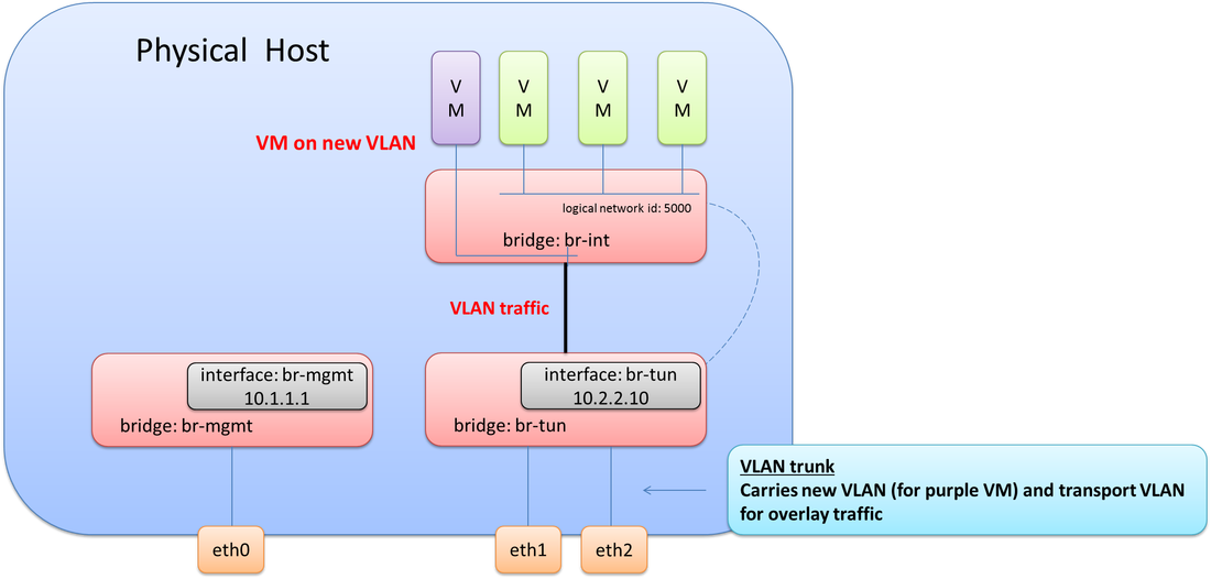
Note: there is no Layer 3 interface for the VLAN on this server.
Let’s throw one more twist in this scenario. The management interface (eth0) went bad! We need to bring management connectivity back up. What does this look like?
Let’s throw one more twist in this scenario. The management interface (eth0) went bad! We need to bring management connectivity back up. What does this look like?
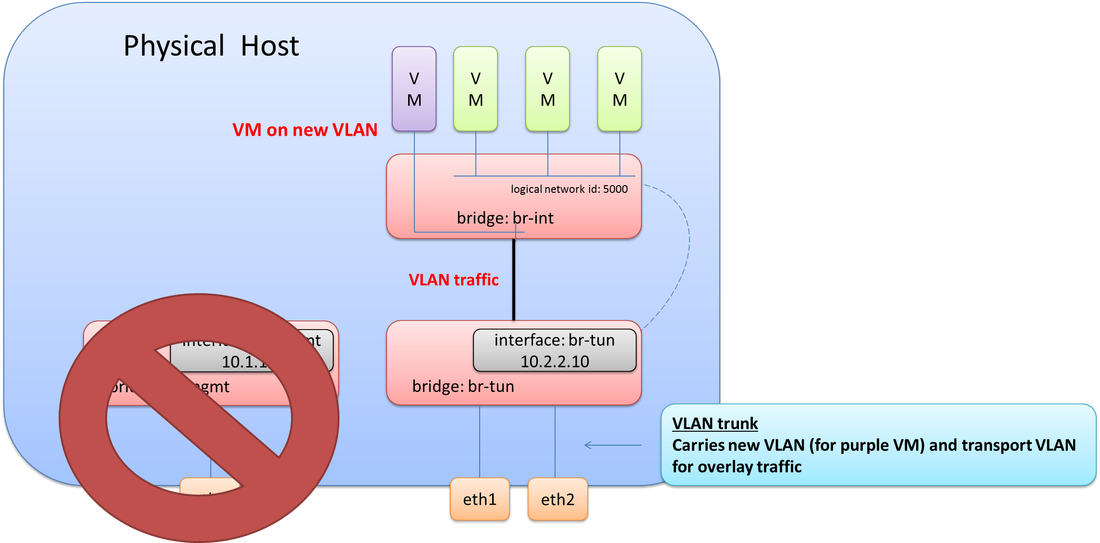
Since an 802.1Q trunk already exists from the previous step when adding in the new purple VM, we just need to add the VLAN used for management onto this trunk. Now all required VLANs are tagged down to eth1 & eth2 (br-tun). The final step here would be to create a new internal port on br-tun, assign it to the management VLAN, and then give it the required IP address from the NIC that failed as depicted in the final diagram.
There you have it! This goes into much more detail on Open vSwitch than in my previous post, and hopefully at some point, I’ll continue with another post that covers even more detail on different interface types and designs for OVS.
And of course, if any of this may be incorrect, please do let me know and I'll get it updated ASAP.
Thanks,
Jason
Twitter: @jedelman8
Sample output of commands mentioned above:
And of course, if any of this may be incorrect, please do let me know and I'll get it updated ASAP.
Thanks,
Jason
Twitter: @jedelman8
Sample output of commands mentioned above:
 RSS Feed
