Jason Edelman's Blog
  • Home
  • About
  • Contact

Facebook Altoona Network Diagram in 2-D

11/15/2014

10 Comments

 
Facebook recently wrote about the network architecture they are using in their new Altoona data center facility.  If you haven't read through their article yet, it's definitely worth the read.

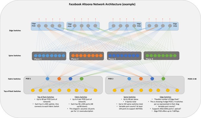
They have a few diagrams that outline the architecture.  One of them is in 3-D.  3-D diagrams are always more difficult for my brain to conceptualize (maybe it's just me), so I re-drew it in a more typical 2-D fashion.
There aren't details on quantity and speeds of ports for the spine and edge switches, so I represented them similar to how they have them in their diagram.  For every downward facing port a spine switch has (across the plane), 2300 servers can be added.  That's the amount of servers per pod.  48 servers per rack * 48 racks per pod = 2300 servers.  Based on the switch types being used, this number could be more, but I'm using the characteristics of 48 x 10G ports for host facing ports + 4 x 40G ports for uplinks.

My diagram depicts 8 racks in the POD and 8 switches per plane.  These numbers would be 48 in a fully built out network/diagram.
Facebook Altoona
Feel free to comment and correct anything I may have mis-represented.

Update 11/17/2014: corrected number of edge pods.

Thanks,
Jason

Twitter: @jedelman8
10 Comments
Michiel Appelman link
11/16/2014 07:55:12 pm

It's not just you, the 3D image took some time to get my head around. Eventually I did make sense out of it -- I think.

Regarding your 2D diagram it seems to show that each spine plane is connected to just one edge pod. In Facebooks 3D diagram I think I see each spine switch in plane N connected to switch N in every edge pod.

Reply
Jason Edelman link
11/16/2014 11:05:11 pm

Now that you say it, I do need to fix the edge pod connectivity. But, it doesn't look like it's every spine in plane N to every edge pod. There are edge pods in the front and the back in their diagram. Each labeled 1-4. It looks like each spine switch in plane N connects to 4 edge switches used for a given plane (not 2 how I had it originally). You can see four links coming out of the edge switches - 1 per spine in that particular plane.

Let me know if you see this.

Reply
Michiel Appelman link
11/17/2014 12:30:08 am

I do see the four links coming out of each edge switch and that each of those links go towards the same plane. However, there is more than one edge switch in each edge pod and each edge switch has their links running towards a different plane. Making the edge pod as a whole connected to each plane.

If for example we look at the front-most edge pod in their 3D diagram we see four edge switches in there: 1, 2, 3 and 4. Switch 4 has four links coming out of it running towards each spine switch of plane 4. Edge switch 3 of that same edge pod, however, connects to each spine switch in plane 3. The same goes for the other switches.

Actually the more I think about it, the more the edge pods look just like server pods without the ToR switches, making it essentially a simple leaf-spine architecture.

Jason Edelman link
11/17/2014 01:49:33 am

I see what you are saying. I think we are saying the same thing, but my edge PODs are shown wrong in the diagram. They have 4 switches in each edge POD numbered 1-4, but for some reason, I was treating 2 of the 4 switches that are number 4, for example, as being in the same edge pod and the other 2, as in the "back" edge pod. I did a mental conversion for what an edge pod is, that was just plain wrong, keep them per-plane, which is not the case.

I'll need to update it to have 4 switches per edge pod (1 per plane) and 4 edge pods to replicate their diagram, although the number of edge pods are technically variable.

Thanks for clarifying!
Jason

Michiel Appelman link
11/17/2014 06:18:45 am

Right! Glad we're both seeing the same thing in this 3D puzzle. Thanks for verifying and keep up the good work!

Reply
Jason Edelman link
11/17/2014 07:20:47 am

Just updated! Hope this is what you are seeing too :)

Reply
tititech
11/18/2014 05:36:16 am

I love it. It is so clear and well done.

Which software did you use to great your amazing diagram?

Reply
Eric Ji
11/18/2014 09:58:05 am

I think there are up to 8 POD's, instead of 48

Reply
Jason Edelman link
11/18/2014 11:28:47 pm

Why would you think that? Each fabric switch has 48 "in" ports and 48 "out" ports.

Reply
Andrea link
5/20/2019 12:45:21 am

Much appreciate you writing this post Jason.

Reply


Leave a Reply.

    Author

    Jason Edelman, Founder & CTO of Network to Code. 


    Enter your email address:

    Delivered by FeedBurner


    RSS Feed


    Categories

    All
    1cloudroad
    2011
    2960
    40gbe
    7000
    Arista
    Aruba
    Big Switch
    Brocade
    Capwap
    Christmas
    Cisco
    Controller
    Data Center
    Dell Force10
    Embrane
    Extreme
    Fex
    Hadoop
    Hp
    Ibm
    Isr G2
    Juniper
    Limited Lifetime Warranty
    Meraki
    Multicast
    N7k
    Nexus
    Nicira
    Ons
    Opendaylight
    Openflow
    Openstack
    Presidio
    Qsfp
    Quick Facts
    Routeflow
    Sdn
    Sdn Ecosystem
    Security
    Ucs


    Archives

    May 2015
    April 2015
    February 2015
    January 2015
    December 2014
    November 2014
    October 2014
    September 2014
    August 2014
    June 2014
    May 2014
    March 2014
    February 2014
    January 2014
    December 2013
    November 2013
    October 2013
    September 2013
    August 2013
    July 2013
    June 2013
    May 2013
    April 2013
    March 2013
    February 2013
    January 2013
    December 2012
    November 2012
    October 2012
    June 2012
    May 2012
    April 2012
    March 2012
    February 2012
    January 2012
    December 2011
    November 2011


    View my profile on LinkedIn
Photo used under Creative Commons from NASA Goddard Photo and Video